- PRACH Sequence in Frequency Domain
- PRACH Sequence in Time Domain
- Example
- prach-ConfigIndex
- zeroCorrelationZoneConfig and Highspeedflag
- prach-FreqOffset
- rootSequenceIndex
- RACH Procedure on Initial Registration
- Livenetwork Example of RACH process for Initial Attach
The first question poping up in your mind when you first hear about the word RACH or RACH Process would be 'Why RACH ?', 'What is the functionality/purpose of RACH process ?', "Why we need this kind of complicated (looks over-complicated) ?'.
For sure, it is not for confusing you :), RACH has very important functionality especially in LTE (and in WCDMA as well). The main purpose of RACH can be described as follows.
i) Achieve UP link synchronization between UE and eNB
ii) Obtain the resource for Message 3 (e.g, RRC Connection Request)
In most of the communication (especially digital comunication regardless of whether it is wired or wireless), the most important precondition is to establish the timing synchronization between the reciever and transmitter. So whatever communication technology you would study, you would see some kind of synchronization mechanism that is specially designed for the specific communication.
In LTE (in WCDMA as well), the synchronization in downlink (Transmitter = eNB, Reciever = UE), this synchronization is achieved by the special synchronization channel (special physical signal pattern). Refer to Time Sync Process page for the details. This downlink sync signal gets broadcasted to everybody and it is get transmitted all the time with a certain interval.
However in Uplink(Transmitter = UE, Reciever = eNB), it is not efficient (actually waste of energy and causing a lot of interference to other UEs) if UE is using this kind of broadcasting/always-on synchronization mechanism. You may easily understand this kind of problem. In case of uplink, this synchronization process should meet following criteria
i) The synchronization process should happen only when there is immediate necessity
ii) The synchronization should be dedicated to only a specific UE
All the complicated/confusing stories in this page is mostly about the process specially designed mechanism to meet these criteria.
Another purpose of RACH process is to obtain the resource for Msg3 (Message 3). RRC Connection Request is one example of Msg3 and there are several different types of Msg3 depending on situation. You would figure out this part in reading through this page and this is not very complicated to understand.
It would be helpful to understand if you think about when 'RRC Connection' happens (or when PRACH process happens if you are interested in lower layer stuffs) in WCDMA. It would also be helpful if you think about when 'Channel Request' happens in GSM UE.
My impression of LTE RACH process is like the combination of PRACH process (WCDMA) and Channel Request (GSM). It may not be 100% correct analogy.. but anyway I got this kind of impression. In LTE, RACH process happens in following situation (3GPP specification, 10.1.5 Random Access Procedure of 36.300 )
E.g. when UL synchronisation status is �non-synchronised�
E.g. when UL synchronisation status is "non-synchronised" or there are no PUCCH resources for SR available.
vi) For positioning purpose during RRC_CONNECTED requiring random access procedure;
E.g. when timing advance is needed for UE positioning
When a UE transmit a PRACH Preamble, it transmits with a specific pattern and this specific pattern is called a "Signature". In each LTE cell, total 64 preamble signatures are available and UE select randomly one of these signatures.
UE select "Randomly" one of these signatures ?
Does this mean that there is some possibility that multiple UEs send PRACH with identical signatures ?
There is such a possibility. It means the same PRACH preamble from multipe UE reaches the NW at the same time.. this kind of PRACH collision is called "Contention" and the RACH process that allows this type of "Contention" is called "Contention based" RACH Process. In this kind of contention based RACH process, Network would go through additional process at later step to resolve these contention and this process is called "Contention Resolution" step.
But there is some cases that these kind of contention is not acceptable due to some reason (e.g, timing restriction) and these contention can be prevented. Usually in this case, the Network informs each of the UE of exactly when and which preamble signature it has to use. Of course, in this case Network will allocate these preamble signature so that it would not collide. This kind of RACH process is called "Contention Free" RACH procedure. To initiate the "Contention Free" RACH process, UE should be in Connected Mode before the RACH process as in Handover case.
Typical 'Contention Based' RACH Procedure is as follows :
i) UE --> NW : RACH Preamble (RA-RNTI, indication for L2/L3 message size)
iii) UE --> NW : L2/L3 message
iv) Message for early contention resolution
Now let's assume that a contention happened at step i). For example, two UEs sent PRACH. In this case, both of the UE will recieve the same T_C-RNTI and resource allocation at step ii). And as a result, both UE would send L2/L3 message through the same resource allocation(meaning with the same time/frequency location) to NW at step iii). What would happen when both UE transmit the exact same information on the exact same time/frequency location ? One possibility is that these two signal act as interference to each other and NW decode neither of them. In this case, none of the UE would have any response (HARQ ACK) from NW and they all think that RACH process has failed and go back to step i). The other possibility would be that NW could successfully decode the message from only one UE and failed to decode it from the other UE. In this case, the UE with the successful L2/L3 decoding on NW side will get the HARQ ACK from Network. This HARQ ACK process for step iii) message is called "contention resolution" process.
Typical 'Contention Free' RACH Procedure is as follows :
ii) UE --> NW : RACH Preamble (RA-RNTI, indication for L2/L3 message size)
In LTE, all the information (data) after PRACH Preamble has its own binary structure meaning that they are translated into a certain data structure. However, the information in PRACH Preamble is represented by purely physical properties. The physical properties that forms the information in PRACH are as follows.
i) PRACH Preamble transmission Timing (t_id)
ii) Location of PRACH transmission in frequency domain (f_id)
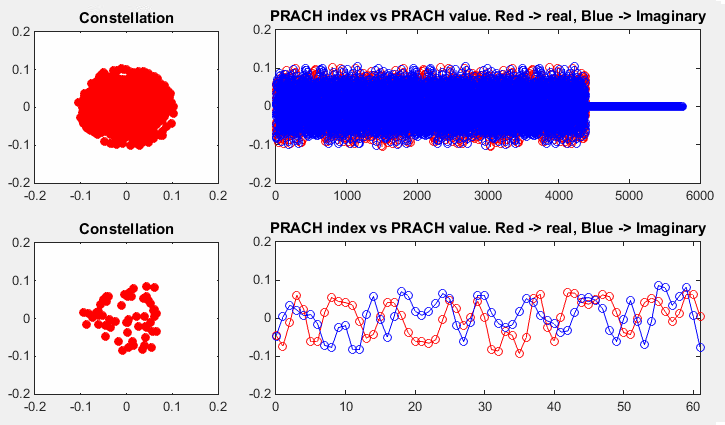
iii) Sequence of the whole I/Q data of PRACH signal (one example shown below)
Following is the PRACH signal transmitted in Time Domain. (You may think this looks different from what you expected. You might have expect to see Zadoff-Chu sequence but this does not look like a Zadoff-Chu sequence. The Zadoff-Chu sequence for PRACH is in Frequency Domain, but this is the time domain sequence. The PRACH Zadoff-Chu is transformed to the time domain sequence as shown below via a transformation that is shown in How to Generate RACH signal section)

From item i) and ii), RA_RNTI is deribed as described in How can we get RA RNTI . From item iii), Preamble Index (RAPID) can be derived.
You may not have much difficulties in understanding the derivation of RA_RNTI but it would not be that simple to understand the derivation of Preamble Index part. Most of the this page with a lot of equations and complex tables are related to this process, but I don't think I did a good job to simply/clearly describe this part. I will add another short sections in the future when I have everything cleared up in my brain. In the mean time, please refer to Matlab LTE Toolbox : PRACH page to get the intuitive (sorry it may not be that intuitive :) image in your brain and read the sections about PRACH Preamble signal generation part in this page. Of course, you would not get everything with single look. Nothing comes easy in engineering :)
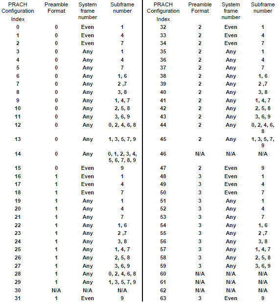
To answer to this question, you need to refer to 3GPP specification TS36.211 - Table 5.7.1-2. This table would give you at which frame and subframe that UE is allowed to transmit a PRACH Preamble. As you see at this table, the prach preamble timing and prach preamble type is determined by PRACH Configuration Index. The, how PRACH Configuration Index is determined ? It is determined by SIB2 parameter prach-ConfigIndex.
Did you open the specification now ? It shows exactly when a UE is supposed to send RACH depending on a parameter called "PRACH Configuration Index".
For example, if the UE is using "PRACH Configuration Idex 0", it should transmit the RACH only in EVEN number SFN(System Frame Number). Is this good enough answer ? Does this mean that this UE can transmit the RACH in any time within the specified the SFN ? The answer to this question is in "Sub Frame Number" colulmn of the table. It says "1" for "PRACH Configuration Idex 0". It means the UE is allowed to transmit RACH only at sub frame number 1 of every even SFN.
Checking your understanding of the table, I will give you one question. With which "PRACH Configuration Idex", it would be the easiest for the Network to detect the RACH from UE ? and Why ?
The answer would be 14, because UE can send the RACH in any SFN and any slots within the frame.
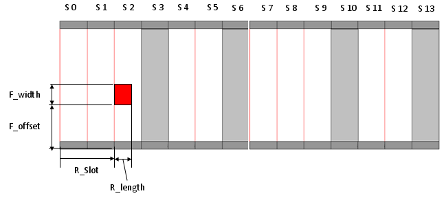
In a big picture, you should know all the dimmensions in the following diagram. (The Red rectangle is PRACH signal).
The R_Slot is determined by PRACH Configuration Index and R_length is determined by Premable format. F_offset is dermined by the following equation when the preamble format is 0~3. n_RA_PRBoffset in this equation is specified by prach-FreqOffset in SIB2. (Refer to 36.211 5.7 Physical random access channel for the details )

